
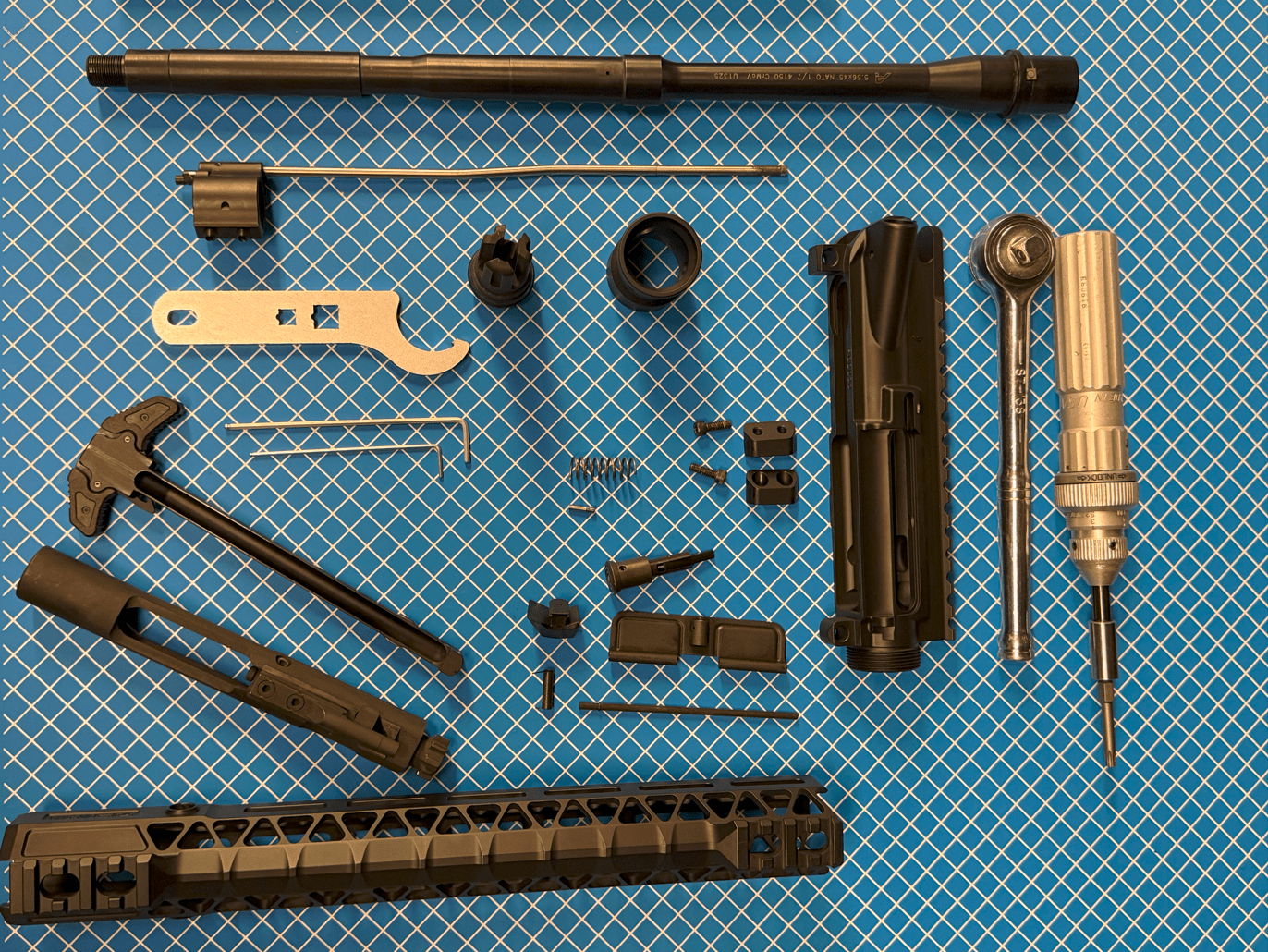
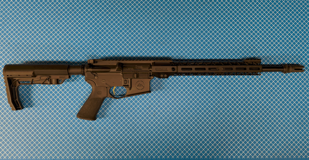
These instructions are designed for assembling the ROAM R-15 Upper Receiver Group, based on standard AR-15 upper assembly practices and ROAM’s lightweight magnesium design.
Upper Receiver Assembly Steps
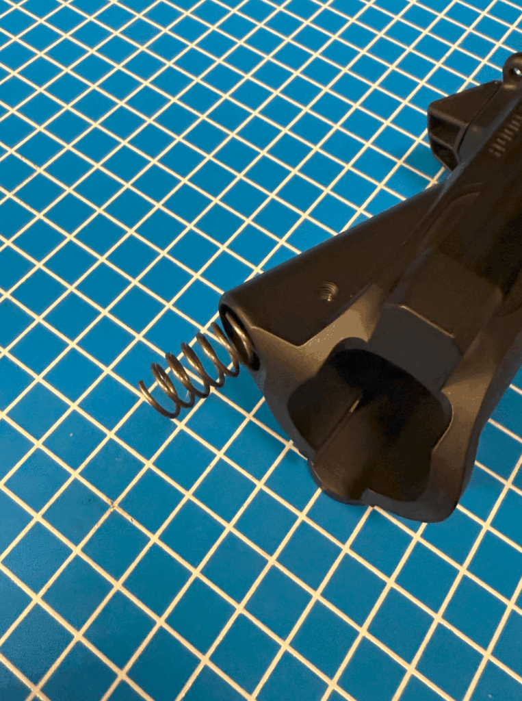
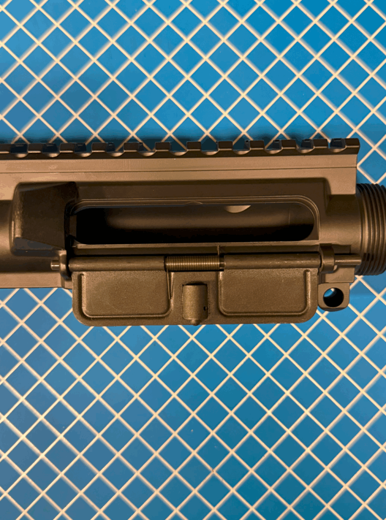
Forward Assist Installation
- Insert the spring into the forward assist.
- Insert the assembly into the forward assist hole on the upper.
- Align the roll pin hole and drive the roll pin in from the bottom up until secure.

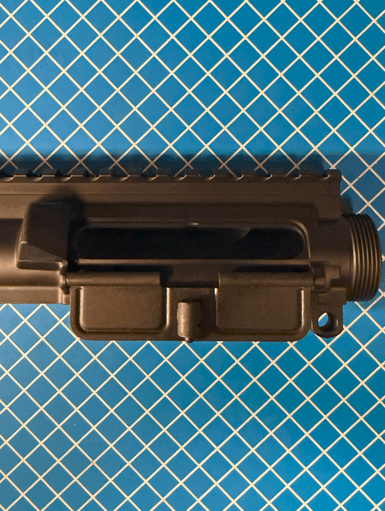
Dust Cover Installation
- If your dust cover pin needs a C-clip and it is not installed clip it into your pin.
- Slide the dust cover into position.
- Insert the cover spring and pin, ensuring the spring is correctly tensioned. The long leg of the spring against the inside of the dust cover and the short leg of the spring against the upper receiver.
- Align the spring and dustcover with the holes in the upper and slide the pin through from front (muzzle end) towards the back of you upper. Your barrel nut will keep the pin from sliding out forward.

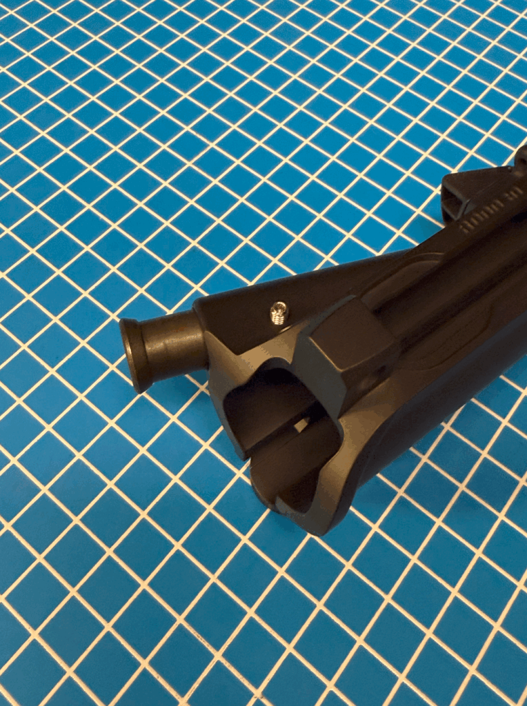
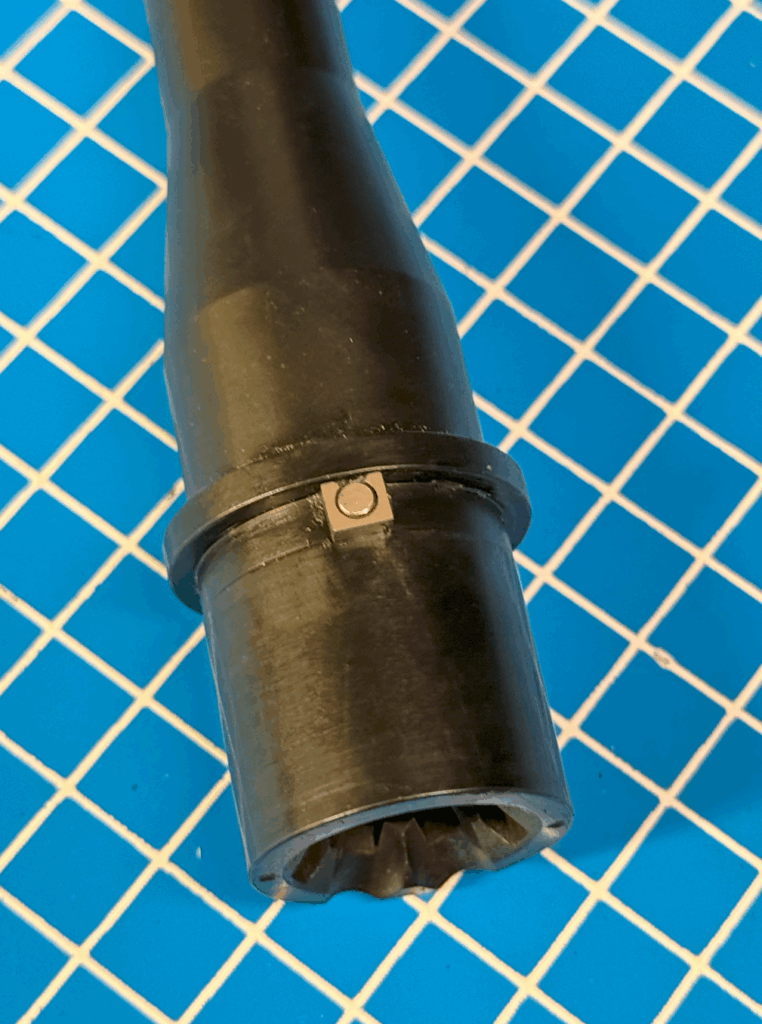
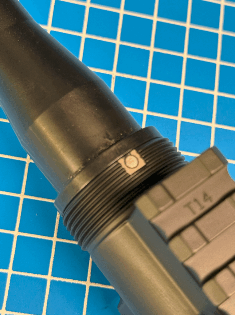
Barrel Installation
- Slide your barrel pin clip over the barrel index pin. A barrel pin clip should be included with any purchase of a ROAM upper receiver. If you are not using a ROAM upper receiver you can disregard information about the barrel pin clip.
- Insert the barrel into the upper receiver and align the index pin and barrel pin clip with the slot in your upper receiver.
- Thread the barrel nut by hand, then torque to manufacturer specifications. 40 ft-lbs is what we recommend. If your barrel nut requires clocking for proper alignment for the gas tube, 30-80ftlbs is the acceptable range.
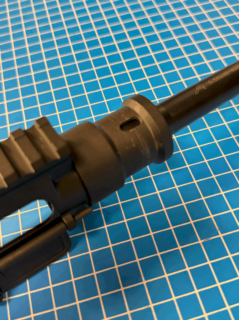
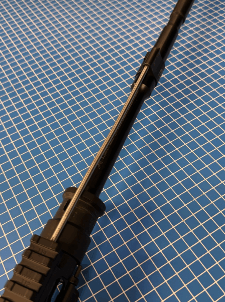
Gas Block and Gas Tube Installation
- Insert the gas tube into the gas block, ensuring the roll pin hole is aligned.
- Drive in the gas tube roll pin.
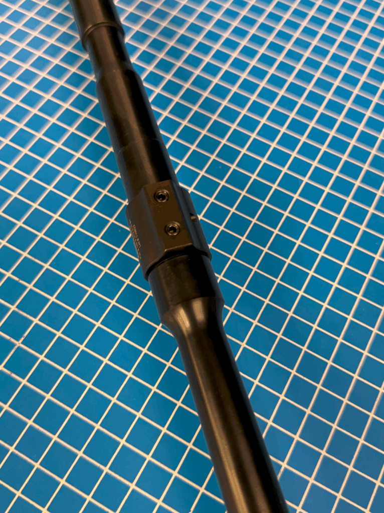
- Slide the gas block assembly onto the barrel, aligning with the gas port.
- Secure the gas block with set screws. Loctite 242 (Blue) is what we recommended on the screws.
- If you are using an adjustable gas block with a screw, we recommend putting some anti seize on the screw or follow the manufacturers recommendation.
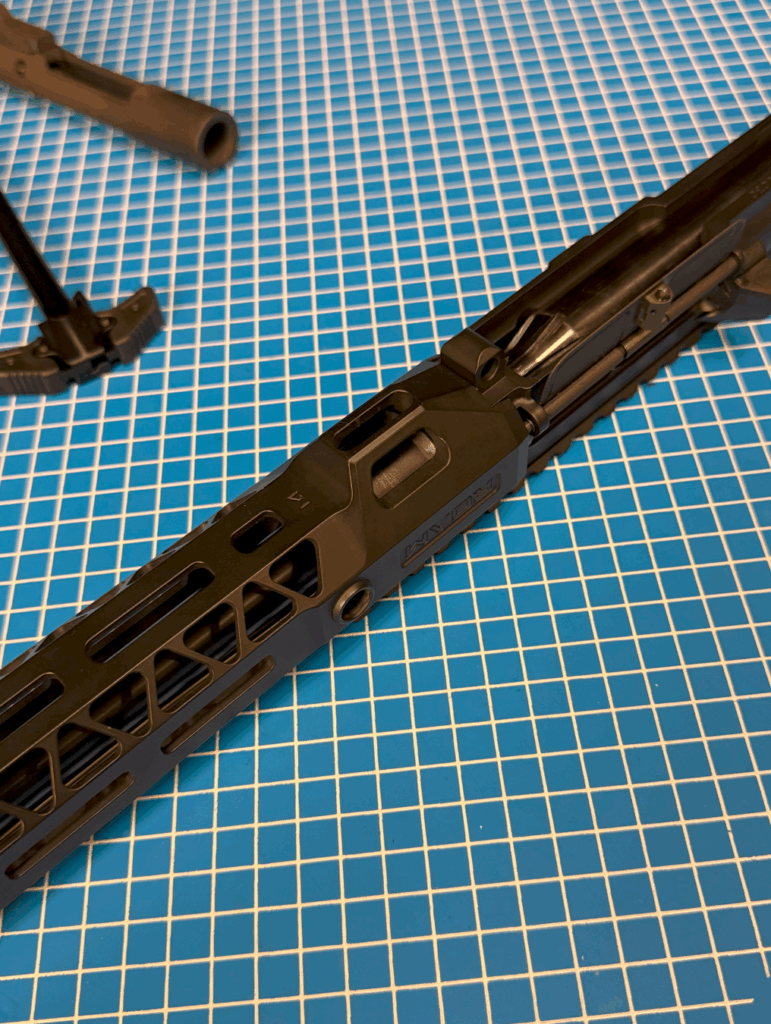
Handguard Installation
- Slide the handguard over the barrel nut and gas block.
- Secure according to manufacturer specifications using mounting screws or clamps.
- Torque mounting hardware as specified.

Muzzle Device Installation
- Install a crush washer or shims as required.
- Thread the muzzle device onto the barrel.
- Torque to approximately 25 ft-lbs or manufacturers recommendations, ensuring proper orientation.
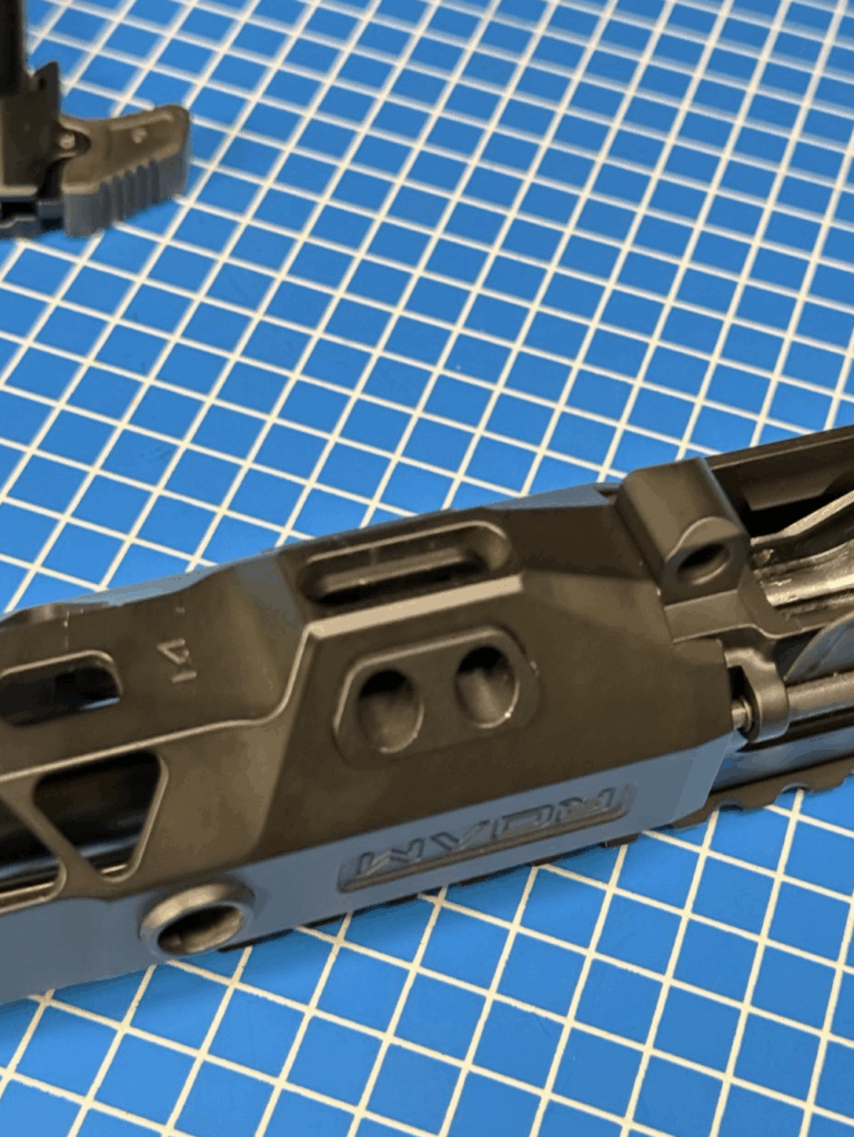
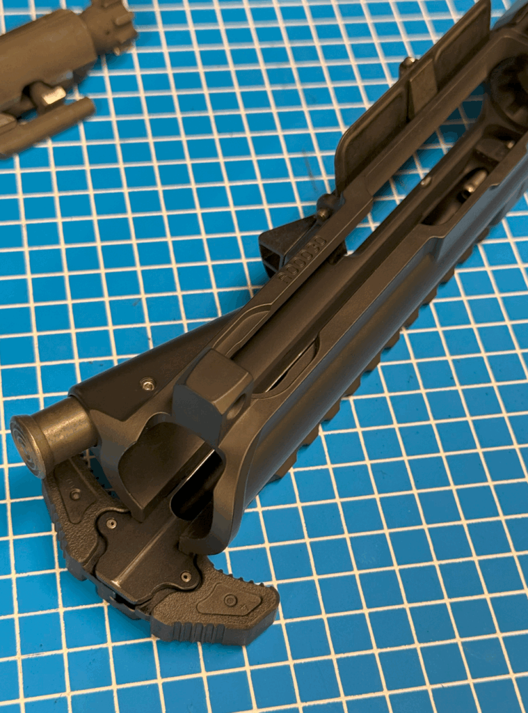
Charging Handle and BCG Installation
- Apply small amounts of gun oil (Like Lucas gun oil) to the rails of the bolt carrier group (BCG) and the top and “fins” of the charging handle.
- Insert the charging handle into the upper receiver channel and stop just under halfway.
- Insert the bolt carrier group (BCG) into the charging handle track. Make sure you cam pin is aligned under your gas tube.
- Push both fully forward until seated.


Bolt Carrier Group Field Stripping Disassembly
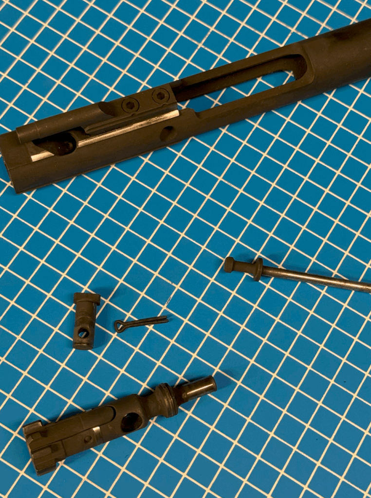
Remove the Firing Pin Retaining Pin
Pull the retaining pin from the side of the carrier.
Remove the Firing Pin
Tilt the carrier and allow the firing pin to slide out.
Remove the Cam Pin
Push the bolt inward, rotate the cam pin 90 degrees, and remove it.
Remove the Bolt
Pull the bolt out from the front of the carrier.
Insert the Bolt into the Carrier
Slide the bolt back into the front of the carrier, ensuring the extractor is oriented on the correct side (ejection port side).
Install the Cam Pin
Align the bolt so the cam pin can pass through its hole. Insert the cam pin and rotate it 90 degrees to lock it in place.
Insert the Firing Pin
Slide the firing pin into the back of the carrier until fully seated.
Insert the Firing Pin Retaining Pin
Push the retaining pin back through the side of the carrier to secure the firing pin.
Function Check the BCG
Pull the bolt forward and push it back to ensure smooth movement. Rotate the cam pin to verify it is locked in properly.
Final Function Checks
- Confirm smooth charging handle operation and BCG cycling.
- Verify dust cover opens and closes as intended.
- Ensure forward assist engages the bolt carrier properly.
- Test bolt catch lock-back with an empty magazine.
You must be logged in to post a comment.